Selection and Fastening Method of Fastening Bolts for the Large Gear of Alumina Mill
Under the background that the mills used in the alumina industry tend to be large-scale. Due to its special grinding process, the temperature inside the mill is too high, which may easily cause the joint surface of the split gear to open. It affects the normal meshing of the open gear of the mill, causing regular vibration of the mill, seriously affecting the service life of the equipment, and even breaking the fastening bolts of the split gear, causing safety accidents.
Alumina is an important link in the aluminum industry chain. In the production process, large pieces of bauxite need to be crushed and ground into small particles. Grinding equipment is the key equipment in the alumina raw material preparation workshop. Due to the harsh environment of high temperatures and high alkali in the preparation of alumina raw materials, the mills used in the alumina industry need to have higher adaptability, safety, and reliability than ordinary mining mills.
At present, the outstanding problem of alumina mills in the industry is that with the development of large-scale mills, the opening phenomenon of the joint surface of the split gear of the mill is becoming more and more serious. The strong alkali and high-temperature environment in the mill causes creep and stress relaxation of the material of the mill gear and its bolted joints, resulting in a gradual decrease in the pre-tightening force and friction in the connection. Finally, the fastening bolt connection at the joint surface of the large gear will fail, which will seriously affect the safe and stable operation of the mill.
Therefore, the selection of fastening bolts for the large gear of the alumina mill is different from that of ordinary mills.
1. Large gear structure of alumina mill
Large-scale mills, especially ball mills, have large gears with large rims and small cylinder diameters. Generally, 3 to 4 rows of bolts are evenly distributed in the radial direction for the fastening of split gears, as shown in Figure 1.
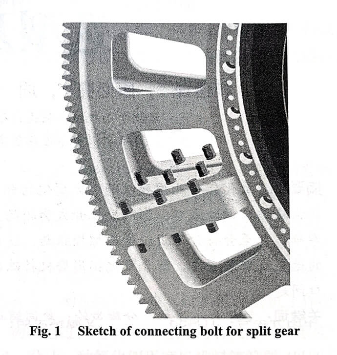
The role of the connecting bolt here is to ensure the reliability and tightness of the split gear connection during the operation of the mill, to prevent gaps or relative slippage at the joint surface of the split gear, and to ensure the smooth transmission of the meshing of the open and large gears. Since the mill gear flange is fastened to the cylinder body and the end cover in three parts, they can be regarded as a whole in a sense. Therefore, the calculation method of the fastening bolts of the split gear of the mining mill is to solve the circumferential force of the gear meshing and to solve a load of each bolt according to the force of the bolt group bearing the turning moment, so as to select the bolts.
The internal temperature of the mill for alumina is as high as about 95 °C, while the surface temperature of the gear wheel is about 50 °C. For planar thin plate materials, the thermal stress formula generated by the temperature gradient is
![]()
![]()
In the formula:
Q is the thermal stress (MPa).
E is the modulus of elasticity (MPa).
α is the coefficient of thermal expansion.
ΔT is the difference between the initial temperature of the material and the surface temperature (°C).
µ is Poisson’s ratio.
The thermal stress of the mill gear from the flange to the tooth surface gradually decreases from large to small. Due to the structural characteristics of the split gear, the rigidity of the flange is the largest due to the three-body fastening with the cylinder body and the end cover. The joint surface of the split gear tooth surface has the weakest rigidity, which is the source of thermal stress release, resulting in deformation and displacement of the split gear, the wedge-shaped opening of the joint surface during operation, and plastic deformation of the fastening bolts.
The thermal stress at the gear flange is the largest. In view of this phenomenon, the joint surface of the split gear is optimized as a non-contact gap design, so that the thermal stress generated during the operation of the mill can be released from here. After thermal-mechanical coupling analysis, the structure-optimized split gear can effectively reduce the opening amount by 25.9%. This theory is a simulation analysis under extreme load conditions, and the actual operation is better than this value. However, the problem brought about by this structural optimization is the radial fastening bolt group of the split gear, and only the bolts close to the tooth root can be effectively fastened. However, the two rows of bolts near the flange cannot be effectively tightened because the connection surface is a clearance fit. Therefore, if the pre-tightening force of the split gear connecting bolt group is not calculated properly, first, the tightness of the connecting bolts cannot be guaranteed, and second, the pre-tightening force applied by the rear bolts will cause the joint surface of the split gear to open during the installation process.
2. Development of calculation program for split gear fastening bolts
According to the particularity of the structure of the aluminum oxide split gear, the fastening bolts of the split gear are calculated. The development process of the calculation program for split gear fastening bolts is as follows: bolt force analysis—calculation of the minimum pre-tightening force required by bolts—bolt type selection—bolt strength check. Based on this, the mathematical model of bolt selection and the mathematical model of the maximum pre-tightening force that can be applied by bolts are established. The mill is heavy-duty impact equipment. When analyzing the force of bolts, only the effectively tightened bolt group and the state with the largest force under extreme conditions are considered.
2.1 Establishment of mathematical model for bolt selection
The establishment of the mathematical model of bolt selection is based on the solution of the minimum pre-tightening force required for fastening the bolts. It is necessary not only to ensure tightness between the split gears but also to ensure that the bolts are not subject to shear force during the operation of the mill. The built mathematical model is as follows:
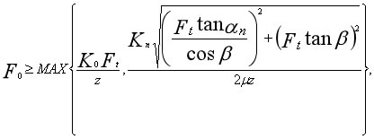
![]()
![]()
In the formula:
F0 is the minimum pre-tightening force required by the bolt (kN).
K0 is the preload coefficient.
Ft is the circular force (kN).
z is the number of bolts in a row on the outer edge of the gear (pieces).
Kn is the reliability coefficient. αn is the gear normal pressure angle (°).
β is the gear helix angle (°).
µ is the friction factor of the joint surface of the preloaded connection.
P is the power of the main motor of the mill (kW).
dr is the pinion pitch circle diameter (mm).
n is the rotational speed of the main motor (r/min).
2.2 Establishment of the mathematical model of the maximum pre-tightening force that can be applied to the bolts
According to the required minimum pre-tightening force of the bolts, the bolts are selected, and after the election, the bolt strength is checked according to the bolt specifications to ensure that the bolts do not undergo plastic deformation during the operation of the mill. The mathematical model of the maximum pre-tightening force that can be applied to the bolt is
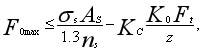
In the formula:
F0max is the maximum pre-tightening force that can be applied to the fastening bolts (kN).
σs is the bolt yield stress (MPa).
AS is the nominal stress cross-sectional area of the thread (mm2).
ns is the safety factor.
KC is the relative stiffness coefficient of the bolt and the connected parts.
According to the above model, the selection of fastening bolts for the large gear of the alumina mill is completed.
3. Installation of the split gear fastening bolts
Due to transportation, installation, weight limit, and other reasons, the key parts of large-scale equipment cannot be manufactured as a whole, and the bolt connection after splitting becomes the weak link of the key parts, which is where failures occur frequently and where maintenance must be paid attention to. The reasonable selection of the fastening bolts of the split gear is only the first step in its reliable application, and the installation is also an important part. A good installation method will bring great convenience to the use and maintenance of the equipment.
As mentioned above, the special structure of the split gear for alumina makes the bolt group radially close to the flange and unable to be tightened according to the normal pre-tightening force. In view of this problem, the installation method of the fastening bolts of the split gear is standardized in combination with the adjustment of the end diameter jump of the large and small gears and the backlash of the teeth during the installation process, so as to avoid the mill operation problems caused by improper installation of the equipment.
3.1 Installation method of the bolt group
Figure 2 shows the key bolt groups for fastening split gears and retightening under thermal conditions using a professional electric torque wrench. The bolt groups at the two joint surfaces are the same. Because the final tightening of the three-body fastening bolts of the mill gear, cylinder body, and end cover is after the end diameter jump of the large and small gears and the tooth side clearance adjustment. Therefore, the order in which bolt groups 1, 2, and 3 are installed is particularly important.
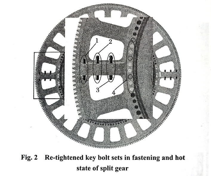
Complete the symmetrical installation of bolt group #1 first. Here is an effective fastening bolt group, which determines whether the split gear is reliable during operation. By setting the maximum torque value of the bolt on the electric torque wrench to ensure the accurate operation of the torque, and check the centering of the split gear and the clearance of the joint surface. Then complete the symmetrical installation of No. 2 and No. 3 bolt groups, and tighten according to 30% ~ 55% of the full torque to enhance the tightness of the split gear.
3.2 Retightening of bolts in hot state
Special attention should be paid to the fact that the thermal state of the mill after the operation will inevitably affect the loosening and deformation of the fastening bolts, so secondary fastening is particularly important. In the hot state, also use an electric torque wrench to retighten the No. 1, No. 2, and No. 3 bolt groups. First, loosen the three-body fastening bolts (No. 4 bolt group) of the gear, barrel, and end cover. When the split gear is centered and the joint surface clearance is intact, follow the installation steps to retighten the No. 1, No. 2, and No. 3 bolt groups. After all retightening, it is necessary to check the end diameter jump and tooth side clearance of the large and small gears again, and it can be used only after all the values meet the requirements.
4. In the end
For the high temperature in the alumina mill, the problem of opening at the joint surface of the split gear is caused. Selecting the appropriate fastening bolts and using the correct fastening tools and methods can solve this problem well. TorcStark has extensive experience in solving bolting problems. For large structures, high-strength bolts have been researched for many years, and high-quality bolt fastening tools have been developed. If you have any questions about bolt fastening, welcome to contact us to get the answer you want!